
AI perception and planning.
Robot Dog
System Architecture
An integrated reference for multi-sensor perception, AI planning and deterministic quadruped motion control.
Explore the Architecture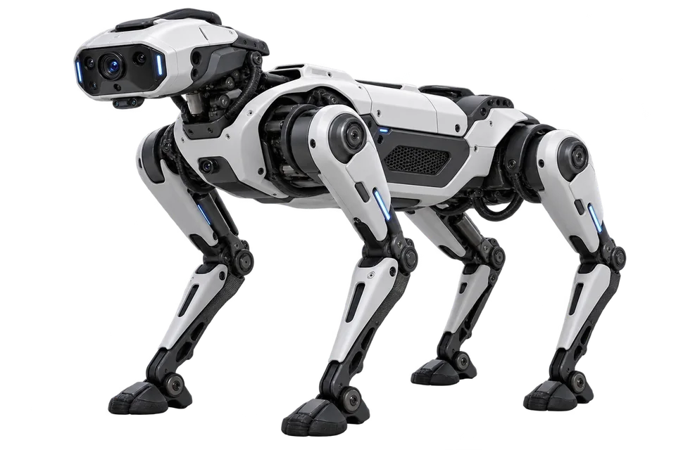
System Architecture Views
Two views of perception, real-time motion and independent protection across the quadruped platform.
01
System Architecture
Sensor observations, estimated state and bounded motion goals meet at a deterministic controller; protection remains independent.
Scroll horizontally to inspect the full signal map →
01
Perception path
Observe, timestamp and plan.
Clock correlation aligns sensor timestamps with RT state; AI sends bounded goals to motion control.
02
Control path
Estimate state and execute the joint loop.
Joint feedback returns from the drives over the cyclic bus to the RT host, then enters state estimation.
03
Independent safety path
Separate inputs, decision and drive response.
Explore a system block
Select a block to explore its role.
Recommended Albatron platforms
Synchronized sensor acquisition.
EtherCAT inertial-state feedback.
Motion-control host; requires a real-time OS, control stack and cycle validation.
Final selection depends on the robot’s power, thermal and interface requirements. TALO-M1000 belongs to the EtherCAT control path; drive control and independent safety hardware remain project-specific.
02
Motion & Control
Inertial sensing, state estimation and deterministic joint control form the motion loop; drive feedback returns through the RT host.
Scroll horizontally to inspect the full signal map →
01
Motion command path
RT control closes the cyclic joint loop.
Drive feedback returns on the cyclic bus to the RT host—not directly to state estimation.
02
State feedback path
Inertial and joint state stay in the control domain.
Estimated state feeds the RT motion controller. Joint feedback reaches the estimator through the RT host.
03
Independent protection
RT status is monitored, not used to command safety outputs.
Safety I/O reaches the drives through an independent path. The safe response is actuator-dependent.
Explore a motion block
Select a block to explore its role.
Motion control and inertial feedback
EtherCAT inertial-state feedback.
Motion-control host; requires a real-time OS, control stack and cycle validation.
Final selection depends on the robot’s power, thermal and interface requirements. TALO-M1000 belongs to the EtherCAT control path; drive control and independent safety hardware remain project-specific.
Reference design, not a certified safety function or a fixed implementation. Interface protocols, clock correlation, drive commands and the safe-state strategy must be chosen and verified for the robot design.
Build for the physical world